Stepper Motor Principles and Control Explained
2023-12-27 10:08:02
What is a Stepper Motor?
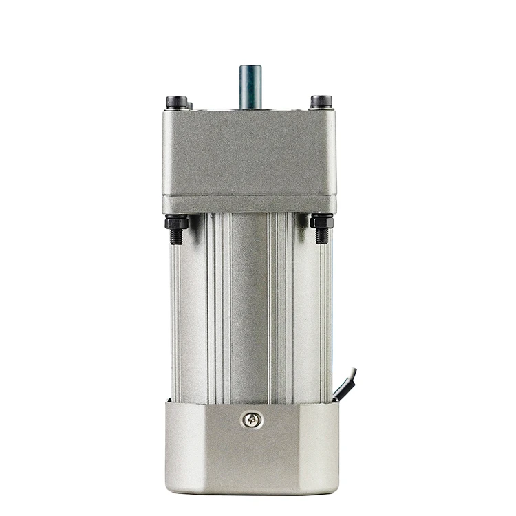
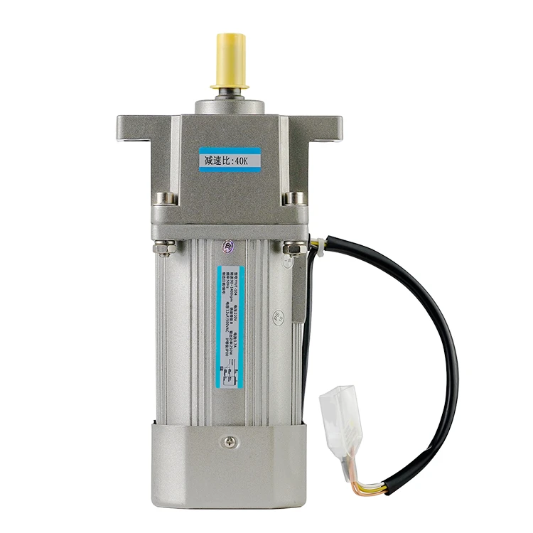
A stepper motor is a device that converts electrical pulse signals into angular or linear displacement in an open-loop control system. By controlling the sequence, frequency, and number of electrical pulses applied to the motor windings, it's possible to control the direction, speed, and rotational angle of the stepper motor. With the addition of a linear motion execution mechanism or a gearbox, more complex and precise linear motion control requirements can be achieved.
A stepper motor typically consists of front and rear covers, bearings, a central axis, a rotor iron core, a stator iron core, stator components, a wave-shaped pad, and screws. The stepper motor is also known as a stepping motor, which utilizes electromagnetic principles to convert electrical energy into mechanical energy. The wire coils wound on the stator teeth of the motor are called coils, windings, or phases.
Stepper Motor Working Principle
Like all motors, a stepper motor has a stationary part (stator) and a moving part (rotor). The stator has toothed protrusions with coiled wire wrapped around them, while the rotor is made of a permanent magnet or a variable reluctance iron core. The rotor in the cross-sectional diagram shown below is a variable reluctance iron core.
When one or more phases of the stator are electrified, the current passing through the coil generates a magnetic field, causing the rotor to align with it. By sequentially applying voltage to different phases, the rotor rotates a specific angle and ultimately reaches the desired position. The working process is shown in the figure below: first, coil A is electrified, generating a magnetic field and aligning the rotor with it; when coil B is electrified, the rotor rotates clockwise 60° to align with the new magnetic field; the same occurs when coil C is electrified. The color of the small teeth on the stator indicates the direction of the magnetic field produced by the stator coil.
In summary, a stepper motor is a special type of synchronous motor. It rotates the rotor by a specific angular step (step angle) by pulsing current through the drive coils. The rotor of a stepper motor is composed of residual pole pairs, and the angular displacement between two poles is called the step angle. When a pulse signal is input, the rotor rotates by one step angle; when multiple pulse signals are input, the rotor rotates by a fixed angle proportional to the number of pulses.
For example, in a 1.8-degree two-phase stepper motor: when both phases are energized, the motor output shaft will remain stationary and locked in position. The maximum torque required to maintain this lock in the rated current is called the holding torque. If the current in one of the phases changes direction, the motor will rotate one step (1.8 degrees) in a predetermined direction. Similarly, if the current in the other phase changes direction, the motor will rotate one step (1.8 degrees) in the opposite direction. When the current through the coil phases is sequentially changed to magnetize, the motor will rotate continuously in a predetermined direction with high precision. For a 1.8-degree two-phase stepper motor, it takes 200 steps to rotate one full cycle.
Types of Stepper Motors
Stepper motors are not made of a single uniform material; they come in various models. Classification by stator phase number includes single-phase, two-phase, three-phase, four-phase, and five-phase, among others.
Classification by rotor structure includes variable reluctance stepper motors (VR), permanent magnet stepper motors (PM), and hybrid stepper motors (HB).
Variable reluctance stepper motors use high-permeability magnetic materials to construct toothed rotors and stators, like the one shown above. They have a simple structure and low production cost, and the step angle can be made quite small, generally three-phase, with a high output torque. The step angle is usually 1.5 degrees. The rotor magnetic circuit of a variable reluctance stepper motor is made of soft magnetic material, and there are multiple phase excitation coils on the stator. The torque is generated using the change in magnetic conductivity. However, its dynamic performance is relatively poor, with more noise and vibration.
Permanent magnet stepper motors use multi-pole cylindrical permanent magnets for the rotor, with toothed stators on the outside. The torque is generated using the attraction and repulsion forces between the rotor and stator. The output is large, the dynamic performance is good, but the step angle is generally larger, usually two-phase, with a smaller torque and volume. The step angle is generally 7.5 degrees or 15 degrees.
Hybrid stepper motors are a combination of the advantages of permanent magnet and variable reluctance stepper motors. They are further divided into two-phase and five-phase: the step angle of a two-phase hybrid stepper motor is generally 1.8 degrees, while the step angle of a five-phase hybrid stepper motor is generally 0.72 degrees. This type of stepper motor has the most extensive applications and is a composite product of PM and VR. The rotor of this type of motor uses toothed rare-earth permanent magnetic material, and the stator has a toothed protrusion structure. This type of motor combines the advantages of both variable reluctance and permanent magnet stepper motors, with a small step angle, large output, good dynamic performance, and is one of the better performing stepper motors. These motors are often used in computer-related equipment.
Control Methods for Stepper Motors
Stepper motors cannot be controlled directly using DC power and require pulse signals to drive their rotation. The distance a stepper motor rotates is directly proportional to the number of pulses applied to the driver (pulse number). The relationship between the stepper motor's rotation (motor output shaft rotation angle) and the pulse number is as follows:
The speed of a stepper motor is proportional to the frequency of the pulse signals applied to the driver. The relationship between the motor's speed [r/min] and pulse frequency [Hz] is as follows (full-step mode):
Stepper motors are typically controlled using related drive chips. There are various drive chips available on the market. Simple applications only require inexpensive drive chips, such as ULN2003A or DRV8834. However, for high-precision control, both the stepper motor and the driver must be accurate. In many engineering fields, specialized drivers are used to achieve more complex control effects.
Stepper Motor Applications
Stepper motors are widely used in situations where precise control of rotational angles is required, such as industrial instruments, medical equipment, robotic systems, and CNC machines. Specific applications include:
Optical drives: moving the read head
Printers: controlling print position
Warehouse automation mechanical arms: precisely positioning and transporting goods
CNC machine tools: determining the position of the main axis
By controlling the pulse number and pulse frequency of the stepper motor, precise control and positioning of rotational motion can be achieved, which is an important reason for the widespread use of stepper motors. Learning to use stepper motors is essential for finding work in the context of industrial innovation.
See What Lunyee Can Do For You
Contact Us
- 8619149417743
- +86-0371-5562 0274
- [email protected]
- Zhengzhou, Henan Province, China
- Mon-Fri: 9:00 - 18:00
