Servo Motor Resolver Wiring
2024-09-03 15:01:30
Servo motors are integral components in many modern automation systems, providing precise control of position, speed, and torque. One of the key elements of a servo motor's feedback system is the resolver, an analog device that helps determine the motor's position and speed. Proper wiring of the servo motor resolver is essential for accurate performance and reliable operation. This article explores the fundamentals of servo motor resolver wiring, detailing the functions of different wire colors, wiring practices, and troubleshooting tips.
Understanding the Resolver
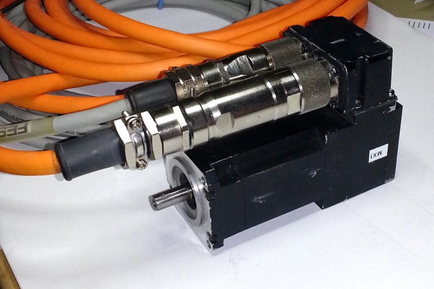
A resolver is an electromagnetic transducer used in servo motors to provide feedback on the motor's shaft position. It works by converting the rotational position of the motor shaft into an electrical signal, which can be interpreted by the motor controller to make necessary adjustments. The resolver operates using the principles of electromagnetic induction, with a primary winding and secondary windings that generate voltage signals corresponding to the shaft's angular position.
Resolver Wiring Overview
The wiring of a resolver typically involves several connections, each with a specific function. Understanding these connections is crucial for ensuring that the resolver communicates accurately with the motor controller. The standard resolver wiring colors and their functions are as follows:
- Excitation Wires (Red and Blue): These wires are responsible for supplying the excitation voltage to the resolver. The excitation voltage is necessary for generating the signals that indicate the motor's position. Typically, the red wire carries the positive excitation voltage, while the blue wire is connected to the ground or negative side of the excitation supply.
- Sine and Cosine Wires (White and Black): The resolver outputs are represented by two signals: sine and cosine. These signals correspond to the sine and cosine of the angle of the rotor. The white wire usually carries the sine signal, while the black wire carries the cosine signal. These signals are used to determine the exact position of the motor shaft.
- Shielding and Grounding: In addition to the standard color-coded wires, resolvers often include shielding and grounding connections. These are critical for minimizing electrical noise and ensuring signal integrity. The shield is typically connected to ground and helps protect the signal wires from external electromagnetic interference (EMI).
Wiring Diagram and Connections
A typical resolver wiring diagram includes the following connections:
Excitation Voltage Supply:
- Red Wire: Connects to the positive terminal of the excitation voltage supply.
- Blue Wire: Connects to the ground or negative terminal of the excitation voltage supply.
Signal Outputs:
- White Wire: Connects to the sine signal input of the motor controller.
- Black Wire: Connects to the cosine signal input of the motor controller.
Shielding and Grounding:
Shield Wire: Connects to the ground to reduce noise and ensure signal clarity.
Steps for Installation and Wiring
To ensure proper installation and reliable operation of the servo motor resolver, adhere to the following best practices:
- Verify Wire Colors and Functions: Before making connections, confirm that the wire colors match the specifications provided by the resolver manufacturer. Incorrect wiring can lead to malfunction or inaccurate feedback signals.
- Ensure Proper Grounding: Proper grounding is essential for minimizing electrical noise and preventing signal interference. Ensure that the shielded wires are correctly grounded to enhance signal integrity.
- Use Quality Connectors and Cables: High-quality connectors and cables reduce the risk of signal degradation and improve the reliability of the resolver feedback system. Choose connectors that are compatible with the resolver's wiring and ensure secure connections.
- Minimize Cable Length: Keep the resolver wiring as short as possible to reduce the potential for signal loss and interference. Excessively long cables can introduce noise and affect the accuracy of the feedback signals.
- Avoid Electrical Noise Sources: Position the resolver cables away from sources of electrical noise, such as high-power cables and other electromagnetic interference sources. Proper cable routing and shielding can help mitigate the impact of external noise.
- Regular Maintenance and Inspection: Periodically inspect the resolver wiring for signs of wear, damage, or loose connections. Regular maintenance helps ensure continued accuracy and reliability in the servo motor system.
Troubleshooting Resolver Wiring Issues
If issues arise with the servo motor resolver, follow these troubleshooting steps:
- Check Wiring Connections: Ensure that all wiring connections are secure and correctly matched according to the color-coding scheme. Loose or incorrect connections can result in signal errors or complete system failure.
- Inspect for Electrical Noise: Verify that the resolver wiring is adequately shielded and grounded. Excessive electrical noise or interference can affect the accuracy of the resolver signals.
- Test Excitation Voltage: Measure the excitation voltage to confirm it is within the specified range. Incorrect excitation voltage can lead to inaccurate resolver signals or operational issues.
- Verify Signal Outputs: Use an oscilloscope or multimeter to check the sine and cosine signals for proper amplitude and waveform. Irregular signals can indicate wiring issues or resolver malfunctions.
- Consult Manufacturer Documentation: Refer to the resolver manufacturer's documentation for specific wiring diagrams, troubleshooting tips, and technical support. Accurate information from the manufacturer can assist in resolving wiring issues effectively.
Conclusion
Proper wiring of the servo motor resolver is crucial for achieving accurate feedback and reliable performance in servo motor systems. By understanding the functions of different wire colors, adhering to best practices for installation, and performing regular maintenance, you can ensure that your servo motor resolver operates effectively. Accurate resolver wiring not only enhances the performance of the servo motor but also contributes to the overall efficiency and reliability of the automation system.
See What Lunyee Can Do For You
Contact Us
- 8619149417743
- +86-0371-5562 0274
- [email protected]
- Zhengzhou, Henan Province, China
- Mon-Fri: 9:00 - 18:00
