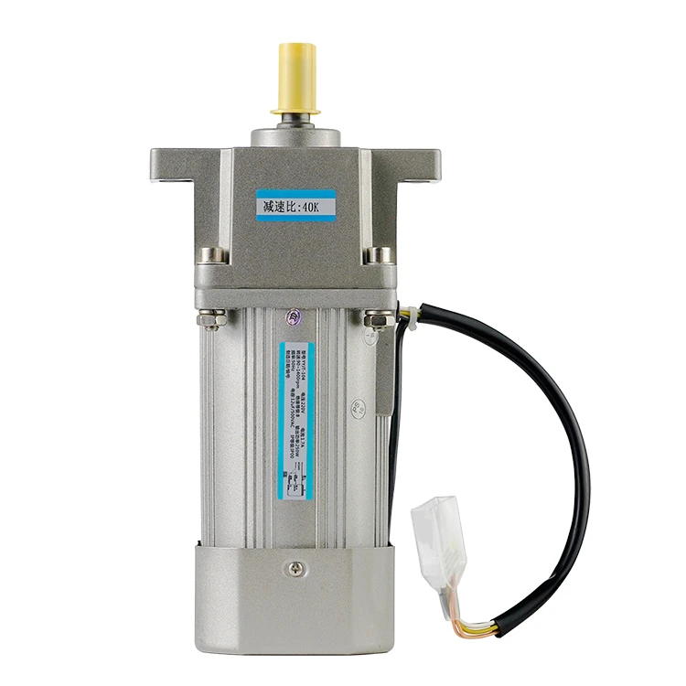
How to test a servo motor?
2024-01-31 17:13:41
Servo motors are widely used in high-precision automated control systems because they can measure specific parameters and provide feedback to the system. However, problems with servo motors can have a huge impact on the entire system. There are some tests you can do to troubleshoot servo motors, and here are some basic steps.
Step 1: Initial Motor Test
Before performing any tests, you will need to ensure that the motor is completely disconnected from any power sources or circuits. This includes unplugging all power sources or disconnecting all control circuits, after ensuring that the motor is completely disconnected, you can follow the steps below:
- Carefully short any two of the motor's three wires together, making sure the connection is secure.
- After disconnecting the motor, gently rotate the motor shaft by hand; close attention needs to be paid to any resistance encountered during rotation. Visible resistance indicates that the motor is operating correctly and that no obstructions or mechanical problems are affecting its operation.
Step 2: Drive power-up test
Particular care is needed when preparing the drive for power-on testing.
- You will first need to refer to the supplied schematic or documentation to properly connect the drive, making sure that all connections are made according to the specified wiring diagram.
- Supply power to the drive, taking care to adjust the input power to the appropriate level (e.g., from 100V to 220V) using a voltage regulator, if necessary.
- Power on the drive and carefully monitor the display for any error messages. If encoder-related errors are displayed, it is important to note that this is the expected result at this stage as the encoder is not yet connected.
Step 3: Encoder connection
Connecting the encoder to the drive is a critical step in the testing process. Please follow the detailed instructions below to ensure a correct and secure connection:
- Refer to the manufacturer's instructions and carefully connect the encoder to the drive following the specified wiring and alignment guidelines.
- After properly connecting the encoder, power on the system and verify that no encoder-related error messages are displayed. This confirms that the encoder has been successfully integrated with the drive.
Step 4: Drive configuration
Configuring the drive is a critical step in the testing process and requires thorough attention to the manual and precise setting adjustments provided.
Refer to the drive manual and carefully configure the drive settings according to the manufacturer's instructions. For example, if setting "Speed Control Mode", carefully follow the guidelines provided to adjust the drive settings accordingly. After configuring the drive, carefully rotate the potentiometer. If the motor does not rotate, refer to the manual for instructions to adjust the toggle switch as directed. After toggling "Servo On", the motor should lock, indicating successful activation. Apply voltage to the SPR/TRQR input pin to start the motor spinning to ensure the motor responds as expected.
Step 5: Switch to position control mode
Changing the drive to "Position Control Mode" is a critical phase and requires the following steps to be performed precisely:
- Change the drive settings to "Position Control Mode" according to the manual instructions, making sure that all parameters are adjusted correctly.
- Connect the motion control card or utilize the MACH3 with the computer parallel port to connect the drive's pulse and direction inputs, following the guidelines provided for proper connection.
- Upon completion of the connection, the motor should begin to rotate. Verify that the output speed is consistent with the intended parameters, e.g. 3000rpm at 500Kpps output rate as specified in the manual.
Step 6: Fine-tuning and testing I/O
Fine-tuning and testing the input/output (I/O) functions is critical to verifying the overall performance of the system. The following are ways to perform this phase precisely:
- Carefully adjust the motion control card and any custom connection boards to ensure compliance with the manufacturer's instructions and guidelines.
- Perform comprehensive output testing using the onboard LED arrays to verify that the signals and outputs are operating as expected. Ensure that the socket is correctly connected to the encoder and outputs a pulse/direction signal, confirming safe and correct integration.
- Rigorously test the I/O inputs using the switches and buttons on the board and strictly follow the guidelines provided to verify the input functionality of the system.
Conclusion
By carefully following these detailed step-by-step procedures and utilizing the specified equipment, you can also effectively test and verify the function of servo motors and drives.
See What Lunyee Can Do For You
Contact Us
- 8619149417743
- +86-0371-5562 0274
- [email protected]
- Zhengzhou, Henan Province, China
- Mon-Fri: 9:00 - 18:00
